| Vorhergehende Seite | Seite drucken |
Jan. 20th, 2007
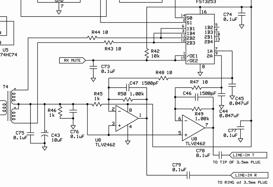
Following the schematic of the V6.1 RxTx receiver mixer:
Here I was wondering, what input impedance the Rx mixer would have. I decided to measure the impedance at the primary of T4, which has 18T primary and 2x9T bifilar secondary. I expected to see the primary inductance parallel to the resistive loading of the mixer. Also I wanted to study the effects of R43, R44 on the input impedance.
Here are my measurement results for a sampling frequency of 7 MHz and a signal of 7 MHz:
 |
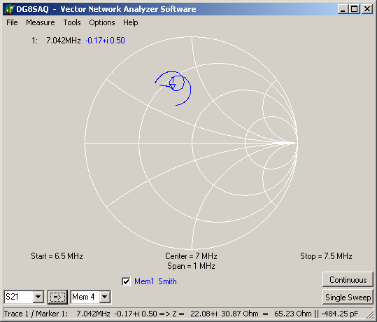 |
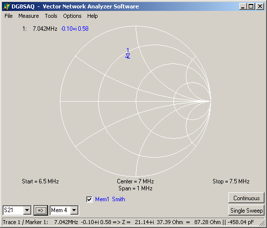
| R43, R44 = 10 Ohms | R43, R44 = 0 Ohms |
You can read the actual impedance at the marker position on the bottom status line of the screenshot above.
Apparently, by bridging R43, R44 one can obtain a match closer to 50 Ohms while obtaining 30% more audio signal.
Interesting is the resonance structure in the impedance (little loop in the Smith chart). This is a dynamic effect of the switch. The additional spike is an artefact due to reception of the sampling frequency by the network analyzer.
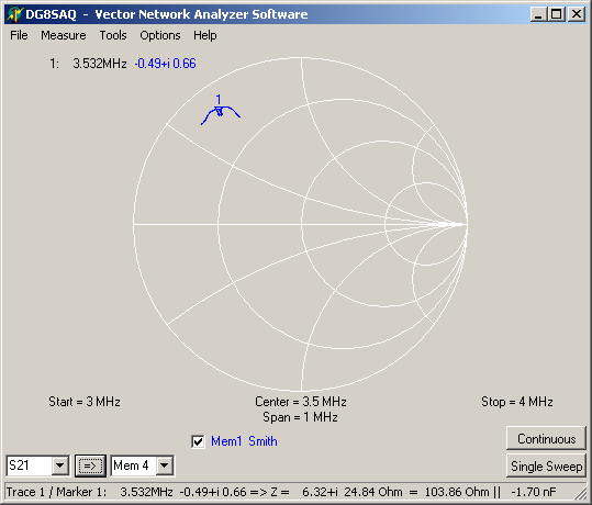
To proof that the resonance loop is a dynamic effect I have performed the same measurement with the sampling frequency reduced to 3.5 MHz. R43, R44 = 10 Ohms for all following measurements:
Here the resonance is gone. The measured impedance is a lot less dependent on frequency.
Tony asked how the impedance changes for subsampling. The following measurements give an answer on that:
Sampling frequency is 3.5 MHz in both cases.
 |
 |
| Sampling 3.5 MHz with 3.5 MHz clock | Subsampling 10.5 MHz with 3.5 MHz clock |
The dynamic resonance is less distinct at subsampling. The impedance doesn't change dramatically (100 Ohms vs. 90 Ohms).
You can download Touchstone files of all measurements by clicking on the diagrams!
I leave the interpretation of these results to all you RF experts out there!
73, Tom DG8SAQ
| Vorhergehende Seite | Seite drucken |