| Vorhergehende Seite | Seite drucken |
Dedicated to all the people who help making this great little
transceiver reality, especially Tony, KB9YIG and Jan, G0BBL. Thanks guys!
Jan. 1st, 2007
This time a rather brief analysis only with respect to my family.
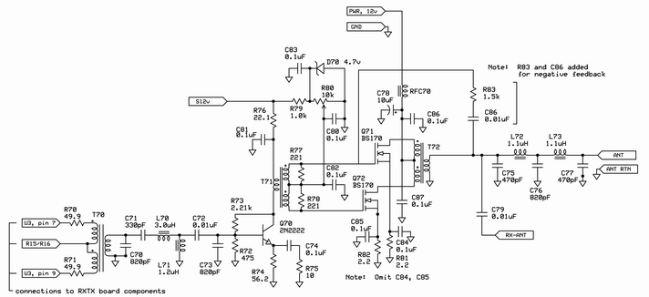
Following the schematic according to which I have assembled the daughterboard:
I have assembled driver and PA WITHOUT input bandpass filter and WITHOUT output lowpass filter. All measurements are performed WITHOUT THESE FILTERS!
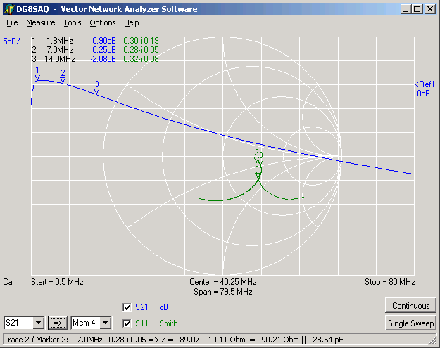
Here is S11 and S21 (-40dB) of the PA measured AC coupled into the base of
Q70 to the secondary winding of T72. The measurement has been performed with a
30dB pad on output and a 10dB pad on input. Reflection calibration has been
performed thru the 10dB pad thus the displayed input impedance of about 100 Ohms
is correct. The small signal gain at 7 MHz is about 40 dB. In this case the TX
draws 90mA (same value without input signal).The output power is in the mW range
here. The current consumption almost doubles when the input signal is increased
to produce 1 W output.
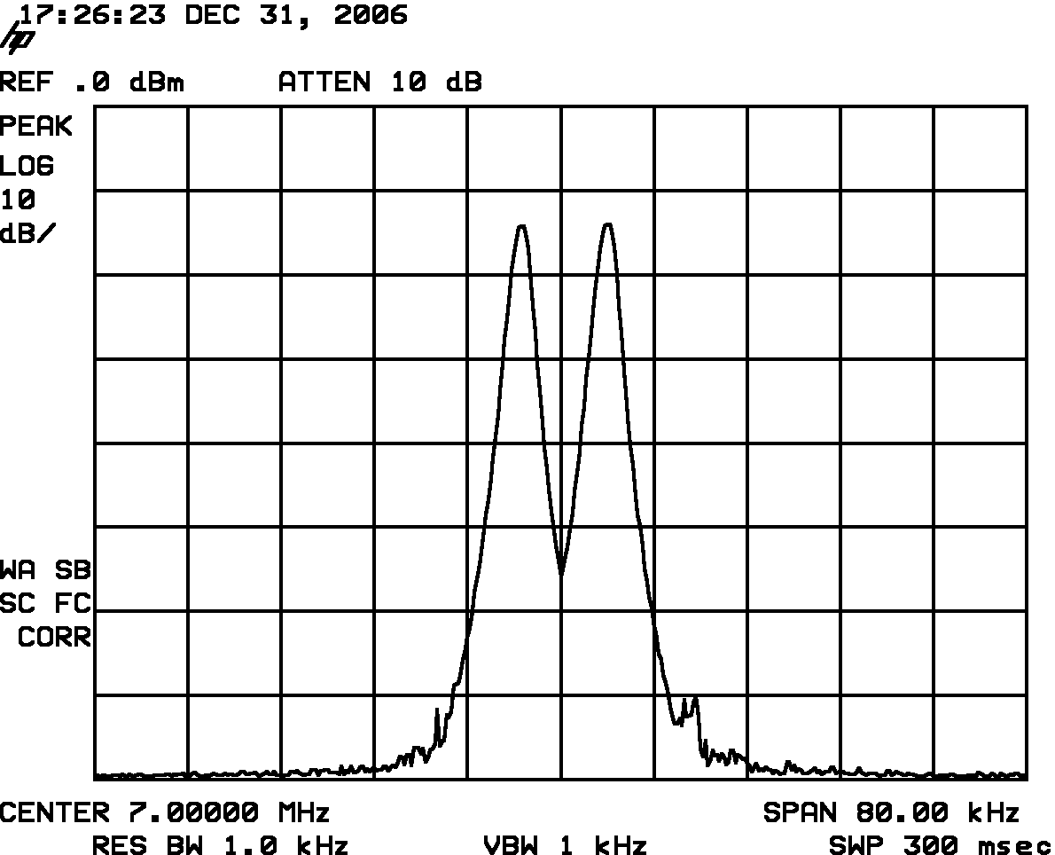
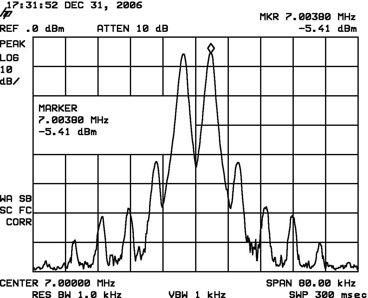
The further IMD-tests I have performed with the combined signals of two 1W signal generators attenuated by 30dB and combined with a 3dB hybrid coupler. Here is my two tone test signal which looks very clean. IMD3 is 55dB below each carrier:
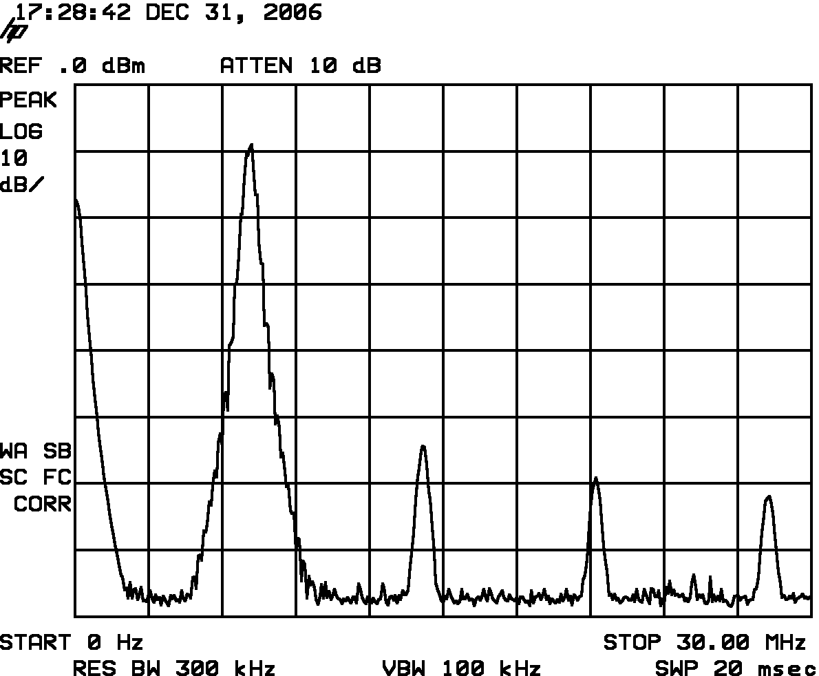
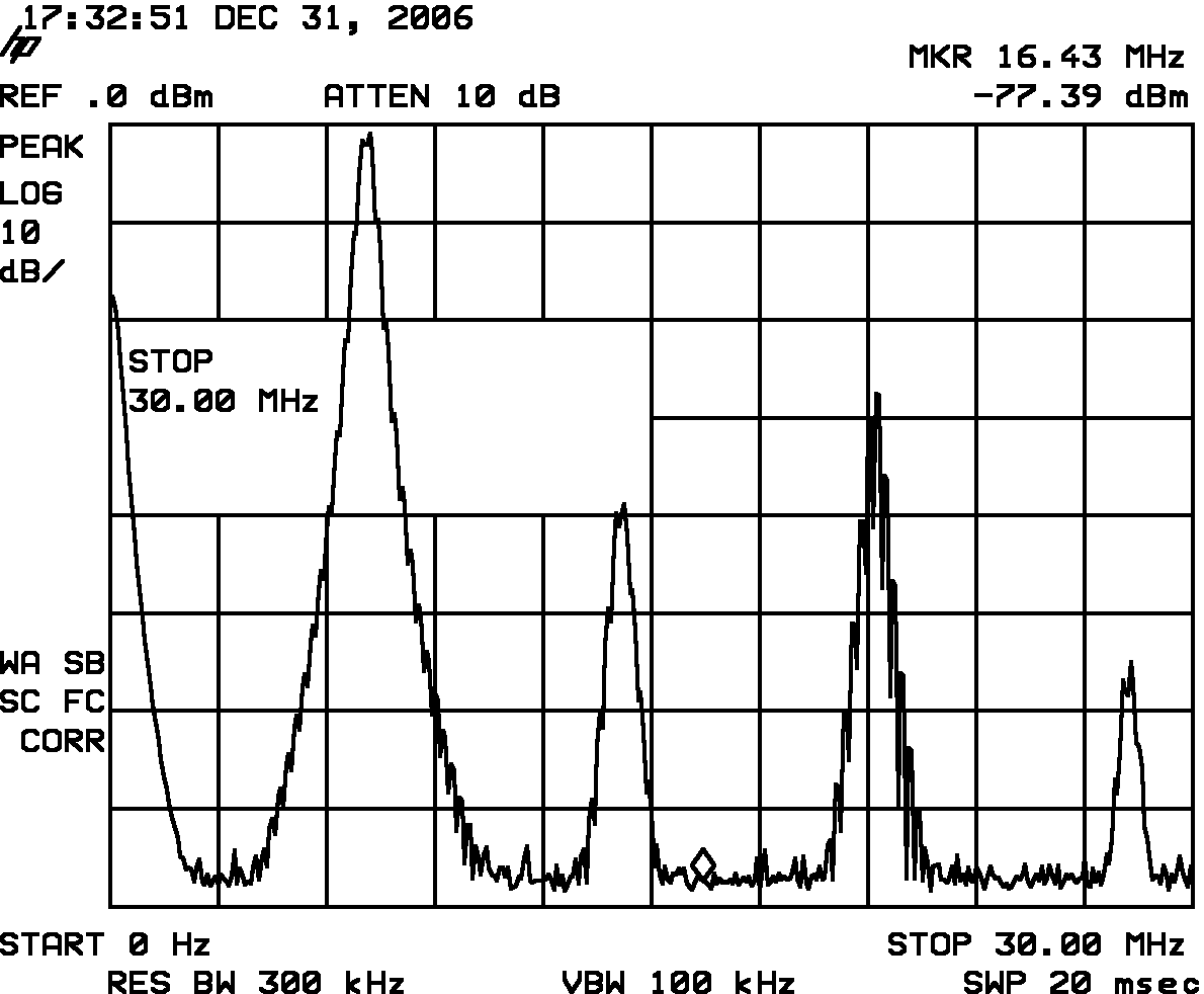
The same signal seen wideband. My signal generators produce considerable harmonics. First harmonic is about 45dB below the carrier. This has to be kept in mind when interpreting the harmonics at the PA output:
Resulting PA output spectrum as seen thru 30dB pads at the output:
Each tone yields a power of 30dBm-6dBm. The PEP is 6dB above each tone so PEP =
30dBm = 1 W here.
I could obtain IMD3 (2*f1-f2) at 38dB below each tone which is good. The bias setting to
obtain this is quite critical, though and can only be adjusted with a spectrum
analyzer. The PA current consumption here is 140mA at 12.0V which reduces
to 88mA without input signal. The currents thru R81/R81 with and without input
signal read 47mA/55mA and 21mA/30mA. Apparrently, one FET systematically draws
9mA more than the other. Here is our source of unsymmetry and IMD. If I reduce
the bias current to lower values I can still get 1W output power but IMD3 goes
up to -25dBc like in Jan's measurements. The same happens when increasing the
bias current.
Here is the wibeband output spectrum with the two tones at 1W PEP. Es expected for a push-pull the first harmonic is below the second harmonic at about -40dBc. Thus most of it comes already from the input signal. Note that this is the harmonic content WITHOUT output low pass filter. I think this is good enough to use the PA with a 40m low pass filter also at 80m output. Suggestion: Make the RxTx a combined 80m/40m device!
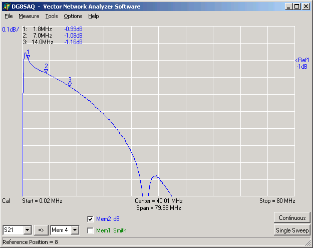
Just for safety I measured T72 before mounting it (I never trust coils I wind with my two left hands :-) ). Here's my result. Reasonably low loss. Note that we are looking at attenuation changes in the hundredth dB range.
Summary:
The daughterboard PA works nicely at 1W output power for 80m and 40m. The cooling works very nicely. I didn't use the silicon washers but simply dipped the transistors into thermal conductive before tightening them with the brass screw and washer.
The only critical item is the setting of the bias current for optimum IMD thus lowest splatter. The optimum is very sharp and I fear it can only be found with a spectru analyzer. You can easily be 10dB off. I guess that's the drawback of using a transistor designed to be a switch.
I suggest that Jan and others set the bias to my values: Measure the voltages across R81/R82 WITHOUT RF input signal and adjust them to the range 100mV...120mV) and see if you get reasonable IMD2 values with a two tone test with IQ-gen. If this works on a few devices, we can be reasonably sure that the optimum IMD setting can also be found with a simple voltmeter.
That's it folks!
73, Tom DG8SAQ
| Vorhergehende Seite | Seite drucken |