| Previous Page | Print Page | Home |
Dedicated to Tony Parks, KB9YIG. Thanks
Tony for this great kit and great support at all times!
Nov. 25th, 2006
First of all I would like to note, that I could not get close to getting 0.4W of distortion free RF out of the original PA transistor 2N3866. I tried 4 transistors of the same type with equally lousy results. So finally I decided to use the 2N3553 instead, which works rather nicely.
While searching the optimally temperature stable biasing network I have come back to the original PA design using RFC1 instead of the published 100 Ohms resistor. And to my surprise I found that the choke did not only increase the gain but also did improve linearity and efficiency. If you experts out there are able to explain this to me, please do so!
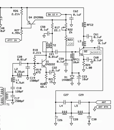
So here is my changes to the original design (see PA section of schematic below)
That's it. So RFC1 in place and no resistor in series to D1.
With this setup I have finally obtained very nice results:
Summary:
Two tone (iqgen, f1 = 14 kHz, f2 = 17 kHz) test with 12.0V power supply:
| PEP out | IC / Q2 | IMD 3 | IMD 5 |
| 0 | 27 mA | - | - |
| 0.23 W | 55 mA | -45 dBc | -47 dBc |
| 0,30 W | 65 mA | -45 dBc | -47 dBc |
| 0.40 W | 72 mA | -40 dBc | -50 dBc |
| 0.53 W | 86 mA | -40 dBc | -43 dBc |
| 0.68 W | 100 mA | -27 dBc | -36 dBc |
| 0.78 W | 118 mA | -21 dBc | -40dBc |
Note, that up to 0.53 W peak output power the PA works quite linearly. Also note, that the average output power is only 1/4 of the PEP in the two toone case. The transistor doesn't get too hot in continuous operation. Heat generation in Q2 ammounts to 0.8 W for 0.53 W PEP two tone.
CW test (iqgen, 14 kHz) with 12.0 V power supply:
As the carrier level is independent of the input signal its origin is NOT
unsymmetries in the switch resistances, but unsymmetries in crosstalk from clock
inputs to switches. This cannot be influenced externally (except thru
compensation techniques).
This implies that the switch should be driven with the highest possible audio
input level to obtain the highest possible carrier suppression.
Spectra:
Here you can see some of the spectra measured with an HP spectrum analyzer thru a professional 30 dB 50 Ohms pad. As the spectrum analyzer has not been calibrated in a long time, I have measured the output powers with a verified 100 MHz scope.
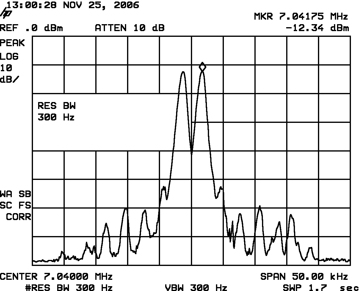
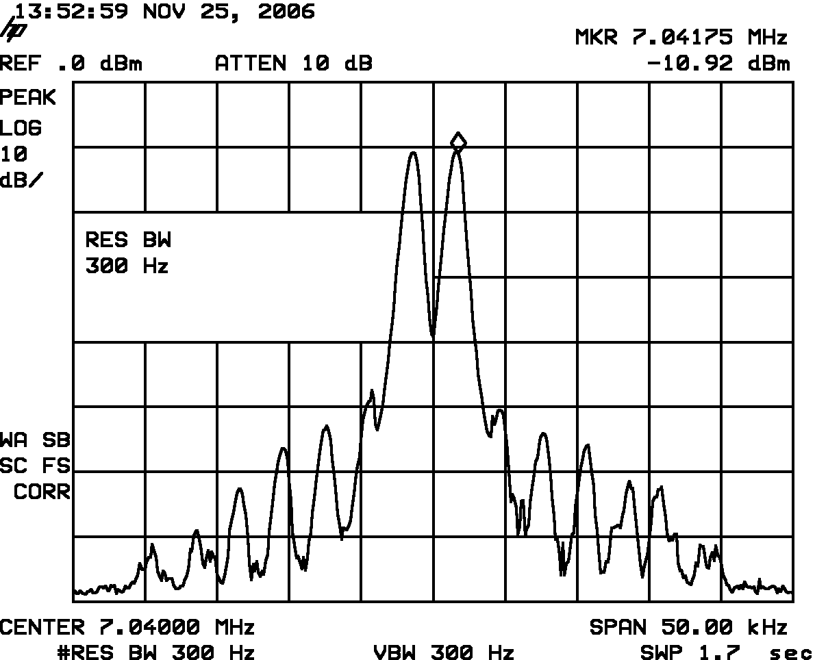
Two tone test with 12.0V power supply:
0.3 Watts PEP (-30 dB pad):
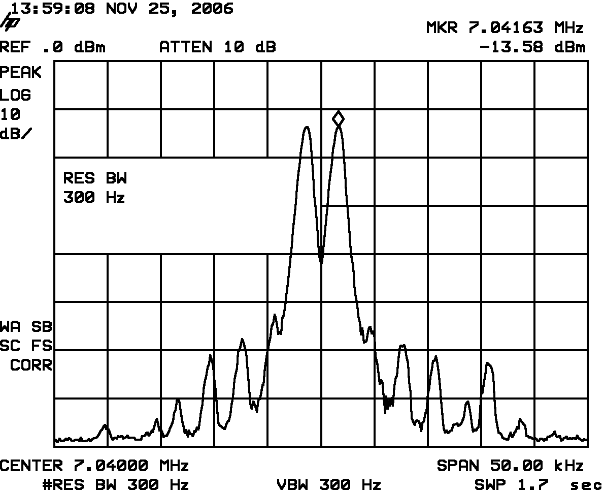
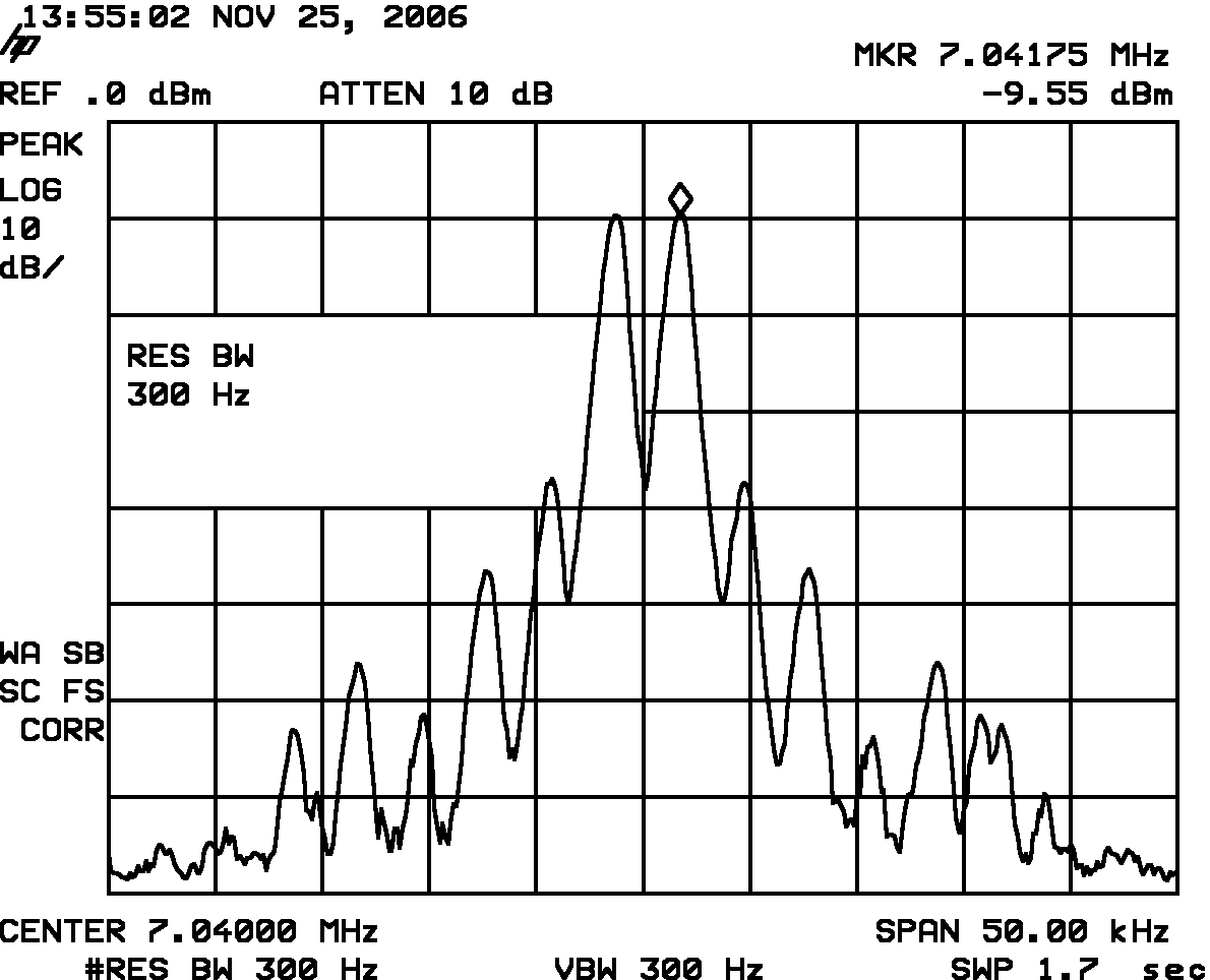
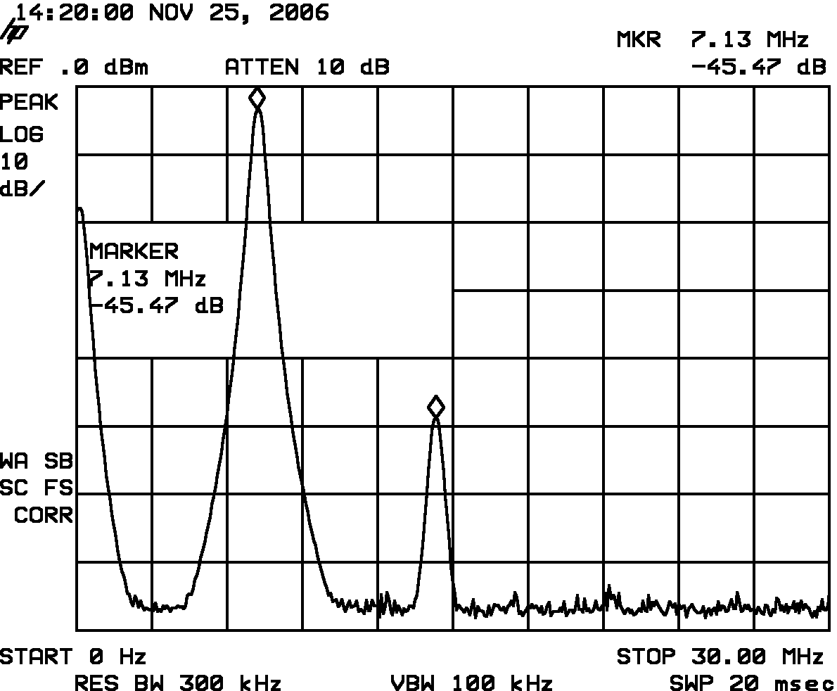
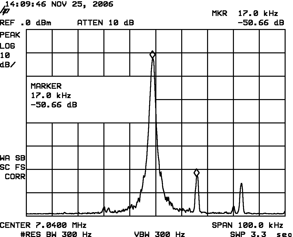
0.4 Watts PEP (-30 dB pad) narrow and wideband:
0.5 Watts PEP (-30 dB pad):
0.68 Watts PEP (-30 dB pad):
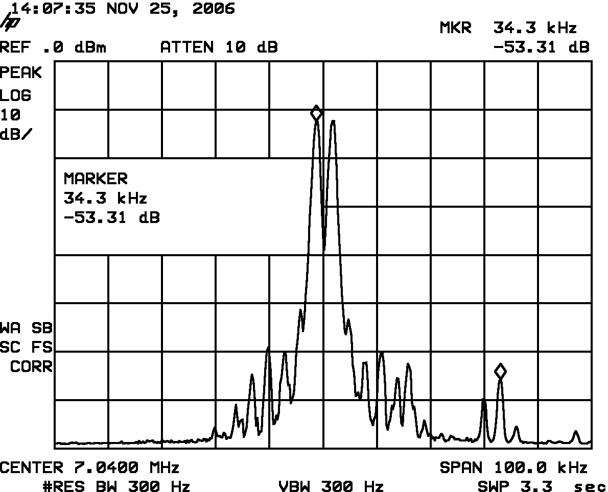
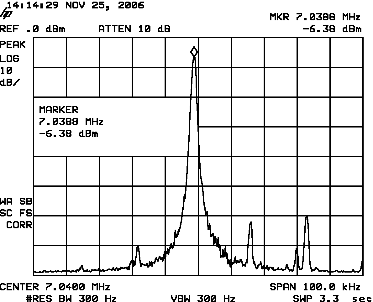
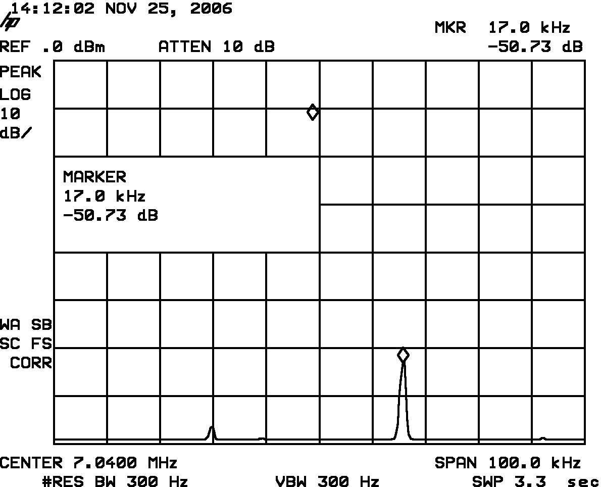
CW test with 12.0 V power supply, IC/Q2 = 107 mA => 33% efficiency of PA (-30 dB pad):
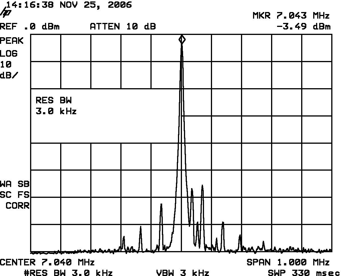
Carrier suppression test with and without input signal:
That's it folks!
73, Tom DG8SAQ
| Previous Page | Print Page | Home |