| Vorhergehende Seite | Seite drucken |
Bernd Kaa DG4RBF has developed a very nice board (SYN500) for the Analog Devices AD9858 1 GSPS direct digital synthesizer, which he has published in the Funkamateur magazine issues 2/2005 and 3/2005. It was designed to cover 500 kHz - 500 MHz with maximum 15dBm output power.
I ordered a cheap main pc board without vias manufactured from a bitmap-file of a scan from the layout out of the Funkamateur magazine. Mounting the 96-pin-DDS was a bit tricky due to lack of a soldering mask. Thanks Helmut DJ0FW for your help!
After tediously having removed all the shorts between the pins
the DDS part worked fine.
While I continued assembling the board I thought about how to extend the
frequency range to the lower side to at least 137 kHz and how to boost the
output power to be at least sufficient for driving a 17 dBm mixer. The frequency
bottleneck in the original design was the transformer between DDS and low pass
filter. I modified that to a 1:1 transmission line BALUN as shown below:
Of course, this device operates only in the MHz range and above as a BALUN, but below the cutoff frequency it still serves as a thru connection from +IOUT to the low pass filter. Thus the lower frequency edge is only limited by the coupling capacitors but not by the transformer any longer. I also recalculated and simplified the low pass filter. I found that by using an elliptic design I could omit 3 of the 7 inductors and still get the same rejection at lower loss.
In order to achieve 20 dBm output power I used a GALI84+ instead of the original GALI6. In order to achieve a linear voltage swing of 7 Vpp at 12V DC supply voltage the GALI84+ wants to see a considerable drain current originally fed ito the device with a series circuit of an RF choke and a resistor. In order to get enough current thru the device the resistor had to be rather low which worked fine for high frequencies being blocked by the RF choke, but in the kHz range the output signal got shorted by the low resistance. Thus, instead of a resistor I used a PNP transistor as current source which works fine:
´The transistor needs to dissipate a couple of Watts thus care is to be taken on cooling it.
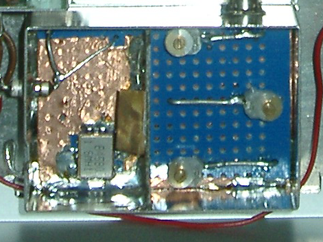
I also designed a very simple 1.2 GHz clock generator. I fed the output signal of a standard 80 MHz TTL clock generator into a 400 MHz SAW-filter. The 400 MHz output signal was fed into a single BFR34A tripler stage with a three resonator bandpass following. On the below picture one can see the SAW-filter (left) and the three 1.2 GHz resonators (right) mimicing an interdigital filter. The TTL oscillator and the transistor are invisible on the bottom of the board. The schematic will be described in detail in the Funkamateur magazine.
All modules were mounted into sheet metal boxes for shielding. All modules were mounted onto a thick aluminum plate which also serves for cooling:
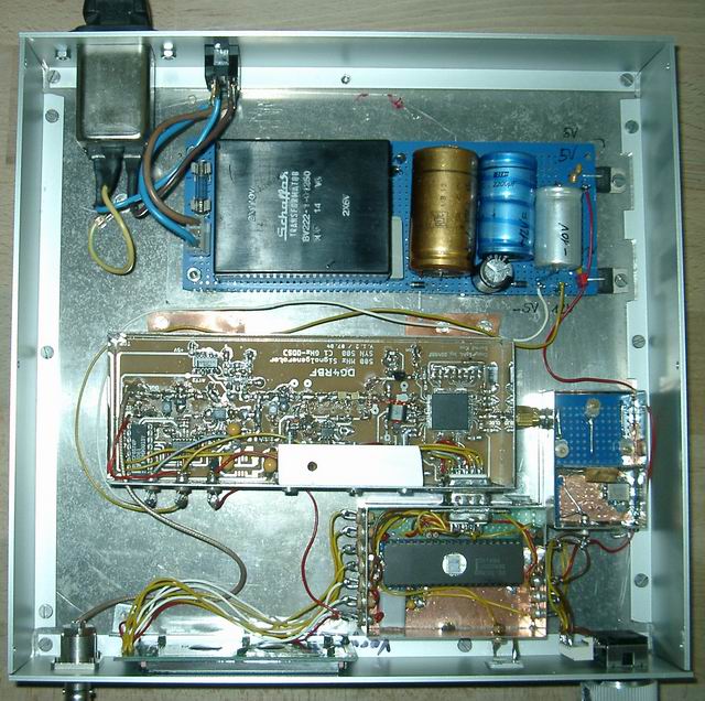
Instead of using the original controller I took an old Intel 8749 (bottom) from my junkbox and wrote a simple firmware in assembler. Using clever algorithms, the old boy was still fast enough to perform all computations for fast realtime wheel tuning even though, the command cycle frequency is only around 500 kHz. And I did it with 32 Bytes of RAM and 1.5 kBytes of EPROM. I felt like 20 years ago!!! If you are interested in the assembler code I will happily share it. Just send me a mail.
With only two controls, a button and a wheel I can control the frequency and the power level. A front view of the operating signal generator is seen below.
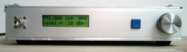
The signal level of 20 dBm is maintained from 10 kHz to 530 MHz. Above the low pass filter cuts in, below the coupling caps decrease the level.
| Vorhergehende Seite | Seite drucken |