| Previous Page | Print Page |
I have assembled the AD9951 DDS board developed by i0CG, Giuliano and i0GLU, Giancarlo and the digital part has worked nicely at once. Thanks to DJ0FW, Helmut, for his help to solder the AD9951 perfectly!
Before connecting the low pass filter to the DDS I decided to measure the transfer function, since I have a nice homebrew network analyzer up to 1.5GHz. The passband looked very nice, but the isolation was far worse than expected.
Low pass performance before layout optimization
Note that the suppression at fclock = 400 MHz is only about 35dB
Layout optimization
After having inspected the filter layout with respect to rf properties I decided to rearrange some of the filter capacitors and add ground vias from top to bottom ground. I have placed a piece of copper foil to the upper (see below picture!) pcb edge to connect top to bottom ground over the pcb edge. Then I replaced the parallel capacitors from their original locations to between the coil solder pads and the copper sheet at the top pcb edge. That did most of the job. I placed the middle parallel C under the 47n coil and disconnected all unused pc tracks. Finally I covered these unused tracks with another piece of copper foil which I connected to the bottom ground with three wired thru holes. See the picture below...
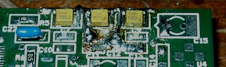
Crucial layout issues to a high isolation low pass filter:
Low pass performance after layout optimization
Note that the suppression at fclock = 400 MHz could be improved by about 40dB to 73dB and remains better than 45dB up to 1,5 GHz. The spikes in the measurements are artefacts due to my scalar network analyzer.
And here is a direct comparison before vs. after layout improvement generated out of the measured data (I have removed the spikes manually!) with the best plotting software ever with name Genplot.
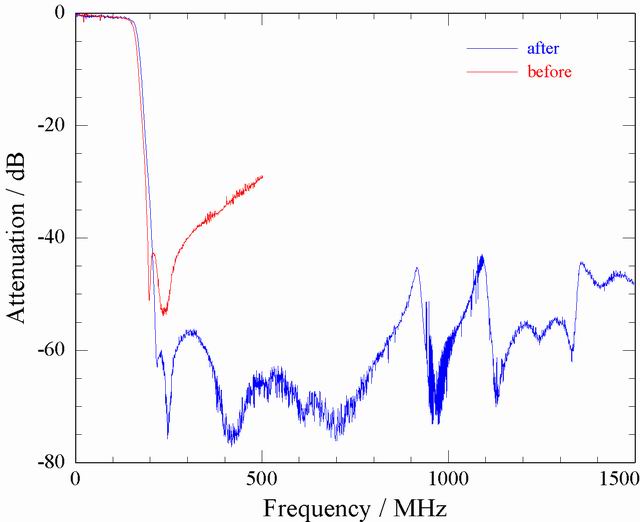
Due to the shortened ground connections the lowpass cutoff frequency is shifted slightly upwards in frequency, which is still fine.
Performance of low pass filter together with amplifier
Since I wanted to find the optimum also for low frequencies I have used 47uF SMD tantalum dc blocking capacitors before and after the amplifier. For good high frequency performance I connected 1nF SMD ceramic capacitors in parallel to the tantalum ones. Surprisingly, I found a 2dB dip in the transfer function at 70MHz!
Explanation: The tantalum capacitors own a small inductivity which forms together with the 1nF capacitors parallel tank circuits resonating at 70MHz.
Solution: Omit the 1nF parallel capacitors and everything works fine...
| Previous Page | Print Page |